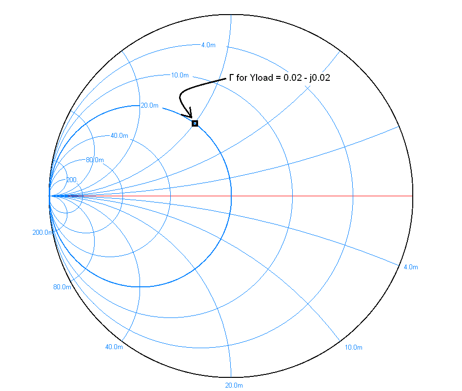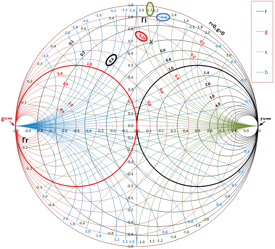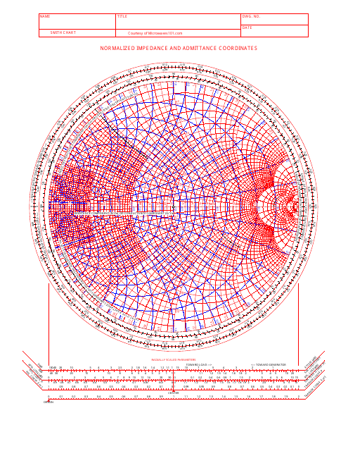

The impedance chart is crucially implemented when working on series loads, all the functionality here is to summate the whole increased impedances. The picture representing impedance smith chart is shown below: Impedance Smith Chart Admittance Smith Chart This impedance of these are the main type where other types are considered as its derivatives. These are generally termed as the usual type of smith charts as they correspond to impedance and functions in an excellent way even with huge loads constructed of many series components where these are the crucial components in the impedance matching and for other RF corresponding operations. \(2 \times \frac\) distance.Smith charts are plotted in two dimensions on the intricate reflection coefficient plane and the chart is generally standardized in impedance or admittance or even both through multiple colors in order to differentiate between those parameters and depending on this scaling, these are primarily categorized as three types. Hence the correct choice is an option (d) 1, 2, 3 only. Smith Chart is also used as an admittance chart so statement 4 wrong. The innermost scale is a protractor (in degrees) and is primarily used to determine the phase of the reflection coefficient and the phase of the transmission coefficient.
ADMITTANCE SMITH CHART GENERATOR
The outermost scale is used to determine distances in wavelengths toward the generator and the next scale is used to determine distances in wavelengths toward the load.

Smith chart is used both impedance and admittance chart. Counterclockwise movement ⇒ Towards the load. Clockwise movement represent ⇒ Towards generator or (away from the load) One complete revolution (360 o) around the smith chart represents a distance of λ/2 online or λ → 720 o. So R L > 50 ohm hence option (1) is correct. If VSWR is finite(not equal to 1) and Minima at load then load will be Purely resistive with R L Z 0. If VSWR is infinite and neither maxima nor minima occur at load, now if we move away from the load and maxima comes first then the load will be Purely inductive.Ħ. If VSWR is infinite and neither maxima nor minima occur at load, now if we move away from the load and minima comes first then the load will be Purely capacitive.Ĥ. If VSWR is infinite and Minima at load then the load will be a Short circuit.ģ. If VSWR is infinite and Maxima at load then the load will be an Open circuit.Ģ. if VSWR is Infinite then the load will be anywhere on the outer circle otherwise inside the circle.ġ. Now According to VSWR identify where do load can exist. hence option (2) is correct.Ĭonsider the points in the diagrams shown below. So load is purely Resistive. Moreover R L < Z 0. If VSWR is finite and equal to 1 then Load is purely resistive with R L = Z 0.ġ. we can see VSWR is finite so we are somewhere inside the circle and as there is minima at load so we are on the line of maxima.Ģ. If VSWR is finite(not equal to 1) and neither maxima nor minima occur at load, now if we move away from the load and maxima comes first then load will be inductive.ĩ.

If VSWR is finite(not equal to 1) and neither maxima nor minima occur at load, now if we move away from the load and minima comes first then load will be capacitive.Ĩ. If VSWR is finite(not equal to 1) and Minima at load then load will be Purely resistive with R L < Z 0.ħ. If VSWR is finite(not equal to 1) and Maxima occur at load then load will be Purely resistive with R L > Z 0.Ħ.

If VSWR is infinite and neither maxima nor minima occur at load, now if we move away from the load and maxima comes first then load will be Purely inductive.ĥ. If VSWR is infinite and neither maxima nor minima occur at load, now if we move away from the load and minima comes first then load will be Purely capacitive.Ĥ. If VSWR is infinite and Minima at load then load will be Short circuit.ģ. If VSWR is infinite and Maxima at load then load will be Open circuit.Ģ. if VSWR is Infinite then load will be anywhere on outer circle otherwise inside the circle.ġ. Concept: Consider the points in diagrams shown below.


 0 kommentar(er)
